 English
 Español
 عربى
عربى


Understanding the Triplex Plunger Pump: An Industrial Powerhouse
In the world of high-pressure fluid transfer, the triplex plunger pump stands as a cornerstone of engineering reliability. Unlike standard centrifugal pumps that rely on velocity to move fluids, these positive displacement machines use the mechanical action of three reciprocating plungers to create consistent, high-pressure flow. The term triplex refers specifically to the three-cylinder configuration, which is a design choice rooted in the need for mechanical balance and a reduction in pressure pulsations. These pumps are essential in environments where fluid must be moved against significant resistance, such as in deep-well injection, high-pressure cleaning, and hydraulic fracturing.
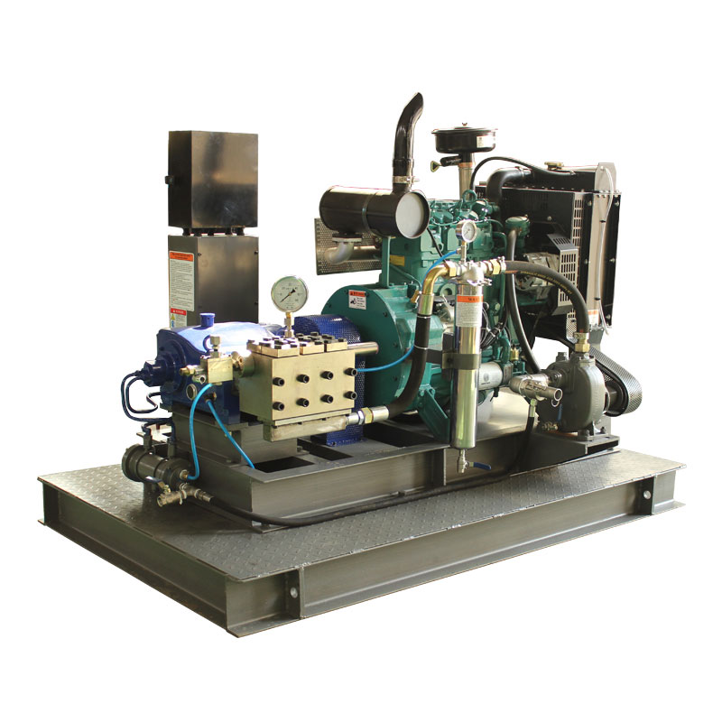
The demand for these systems often necessitates independent power sources, leading to the development of the Diesel Triplex Plunger Pump. By pairing the robust mechanical advantages of a triplex head with the high torque and portability of a diesel engine, industries can operate in remote locations where electrical infrastructure is non-existent. This detailed exploration covers the nuances of their internal mechanics, the physics of fluid displacement, and the operational standards required to maintain these high-performance units over long service lives.
To truly appreciate the triplex design, one must look at the evolution of pump technology. Single or duplex pumps often suffer from significant "water hammer" effects and uneven flow rates. By introducing a third plunger, the timing of the discharge strokes overlaps in a way that creates a much smoother output. This stability is critical for protecting downstream piping and ensuring the longevity of the pump's internal seals and valves.
Core Components of a Triplex Plunger Pump
A triplex plunger pump is divided into two primary sections: the power end and the fluid end. Each section plays a vital role in converting rotational energy into linear hydraulic pressure.
The Power End
The power end is the mechanical heart that drives the reciprocating motion. It typically consists of a crankshaft, connecting rods, and crossheads. The crankshaft converts the circular motion of the motor or engine into a back-and-forth movement. Because the crankshaft has three throws offset by 120 degrees, the three plungers operate in a staggered sequence. This offset is the secret to the continuous flow profile associated with triplex systems.
The Fluid End
The fluid end is where the actual pumping occurs. It contains the pump manifold, the plungers, and the valve assemblies. The plungers, often made of high-strength ceramic or stainless steel with specialized coatings, slide in and out of the fluid chamber. Unlike a piston pump, where a seal moves with the piston, a plunger pump uses stationary high-pressure seals through which the plunger slides. This design allows for significantly higher operating pressures, often exceeding several thousand pounds per square inch.
- Suction Valves: These allow fluid into the chamber during the retraction stroke.
- Discharge Valves: These open during the forward stroke to push fluid into the system.
- Plunger Packing: The critical seal that prevents fluid from leaking back into the power end.
- Manifold: The internal piping that distributes fluid to each of the three cylinders.
The Mechanical Workflow: How It Works
The operation of a triplex plunger pump follows a strict four-stage cycle for each of its three cylinders. Because these cycles are staggered, the pump provides a nearly constant stream of pressurized fluid.
- The Suction Stroke: As the crankshaft rotates, the connecting rod pulls the plunger backward. This creates a vacuum within the cylinder. The atmospheric pressure (or supply pressure) forces the suction valve open, filling the chamber with fluid.
- Transition: Once the plunger reaches its maximum rearward position, the suction valve closes due to spring tension and the initial change in pressure.
- The Discharge Stroke: The crankshaft continues its rotation, pushing the plunger forward into the fluid-filled chamber. Since the fluid is nearly incompressible, the pressure rises rapidly.
- Ejection: When the internal pressure exceeds the pressure in the discharge line, the discharge valve is forced open. The plunger pushes the fluid out of the manifold and into the application line.
In a Diesel Triplex Plunger Pump, this cycle can occur hundreds of times per minute. The speed of the diesel engine is often controlled through a gearbox or belt drive to match the specific flow requirements of the task. The volumetric efficiency of these pumps is remarkably high, often exceeding 90 percent, meaning almost all the fluid that enters the chamber is successfully discharged at pressure.
Technical Specifications and Performance Metrics
Selecting the right pump requires an understanding of how mechanical input translates to hydraulic output. The following table illustrates the typical performance relationship in industrial-grade triplex systems.
| Parameter | Metric Units | Operational Impact |
| Flow Rate | Liters per Minute (LPM) | Determines the speed of the operation. |
| Maximum Pressure | Bar / PSI | Determines the force available for the task. |
| Input Speed | RPM | Affects the wear rate of seals and valves. |
| Plunger Diameter | Millimeters (mm) | A larger diameter increases flow but requires more torque. |
Engineers must balance these factors. For instance, increasing the plunger diameter will provide more volume, but the diesel engine must be capable of providing the necessary torque to overcome the resistance at that larger surface area. This is why diesel engines are favored; their torque curves are ideally suited for the heavy, pulsing loads of a triplex pump.
The Advantage of Diesel Drive in Triplex Systems
While electric motors are common in stationary factory settings, the diesel-driven triplex pump is the standard for mobile and rugged applications. There are several technical reasons for this preference.
Portability and Autonomy
In oil fields, mining sites, or large-scale construction projects, access to a high-voltage power grid is often limited. A diesel engine provides a self-contained power source that can operate for hours on a single tank of fuel. This autonomy is vital for emergency response units, such as high-pressure fire suppression systems or mobile hydro-demolition rigs.
Variable Speed Control
Diesel engines offer excellent variable speed control via the throttle. Since the flow rate of a positive displacement pump is directly proportional to its RPM, the operator can finely tune the pump output by simply adjusting the engine speed. This eliminates the need for expensive variable frequency drives (VFDs) required by electric motors in the field.
Durability in Harsh Environments
Industrial diesel engines are built to withstand dust, moisture, and extreme temperature fluctuations. When paired with a triplex pump featuring a robust cast-iron crankcase and stainless-steel fluid end, the resulting machine is capable of 24/7 operation in the most punishing climates on Earth.
Maintenance Protocols for Longevity
The longevity of a high-pressure system is entirely dependent on the rigor of its maintenance schedule. Because the plungers and seals are subject to constant friction and high-pressure cycles, they are considered "wear items."
- Lubrication: The power end requires high-quality gear oil. Monitoring for metal shavings in the oil can provide early warning of bearing failure.
- Seal Inspection: Plunger packings should be inspected for leaks. A small drip is often intentional for cooling, but excessive leakage indicates the need for replacement.
- Valve Seating: Over time, the valves and seats can become pitted or "washed out." Regular inspection ensures that the pump maintains its volumetric efficiency.
- Filtration: The fluid entering the pump must be free of large particulates. Abrasive solids can score the plungers and ruin the high-pressure seals in a matter of hours.
By implementing a proactive maintenance strategy, operators can achieve thousands of hours of service before requiring a major overhaul. This is particularly important for diesel-powered units where downtime can result in significant financial losses in field operations.
Common Industrial Applications
The versatility of the triplex design allows it to serve a diverse range of industries. Its ability to handle different fluids—from water and oil to chemicals and slurries—makes it an indispensable tool.
Oil and Gas Industry
In the upstream sector, triplex pumps are used for well stimulation, cement injection, and produced water disposal. The high-pressure capabilities allow operators to overcome the natural pressure of deep underground reservoirs.
Industrial Cleaning and Hydro-Demolition
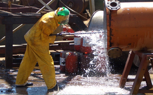
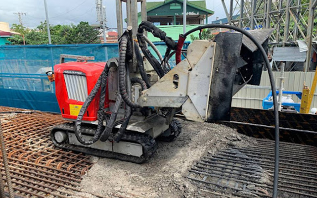
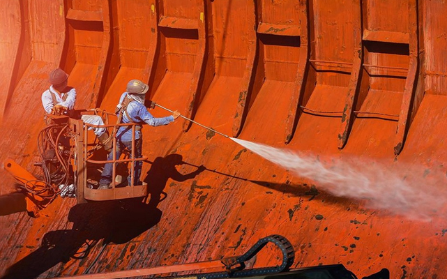
Water jetting at pressures exceeding 1,000 bar can cut through concrete or strip paint from ship hulls. The steady flow of a triplex pump ensures that the cutting tool remains effective without the surging that would occur with a lesser pump design.
Agricultural Irrigation and Chemical Injection
For large-scale farming, these pumps can move water across vast distances or inject fertilizers into irrigation lines with extreme precision. The durability of the diesel-driven variant makes it ideal for use in remote fields.
Technical Challenges and Solutions
No mechanical system is without challenges. For triplex pumps, the primary issues involve cavitation and pulsation control.
Cavitation occurs when the suction pressure is too low, causing vapor bubbles to form and then collapse violently against the pump components. This can be prevented by ensuring a proper Net Positive Suction Head (NPSH) and using booster pumps if the supply tank is located far from the main unit.
Pulsation is an inherent characteristic of reciprocating pumps. While three cylinders reduce this significantly compared to one or two, some vibration remains. To solve this, engineers install pulsation dampeners—gas-filled vessels that absorb pressure spikes and provide an even smoother flow to the downstream equipment.
Frequently Asked Questions (FAQ)
Q1: Why are three plungers used instead of two or four?
A1: Three plungers provide the best balance between mechanical simplicity and flow smoothness. The 120-degree offset ensures that at least one plunger is always in a discharge phase, minimizing the "dead spots" in pressure that occur in duplex pumps.
Q2: What is the difference between a piston pump and a plunger pump?
A2: In a piston pump, the seal is attached to the moving piston and rubs against the cylinder wall. In a plunger pump, the seal (packing) is stationary in the pump head, and the smooth plunger slides through it. Plunger pumps are generally preferred for higher pressures.
Q3: How do I know when the packing needs to be replaced?
A3: An increase in water leakage from the weep holes or a noticeable drop in discharge pressure usually indicates that the packing is worn. Regular monitoring of the "weep" rate is the best diagnostic tool.
Q4: Can a triplex pump run dry?
A4: No. Running a plunger pump without fluid will cause the seals to overheat and fail almost instantly due to lack of lubrication and cooling provided by the pumped medium.
Q5: What are the benefits of a diesel engine over an electric motor for these pumps?
A5: Diesel engines offer total portability, high torque at low speeds, and the ability to vary the pump's flow rate easily via engine RPM adjustments without needing complex electrical controllers.