 English
 Español
 عربى
عربى


Understanding High Pressure Plunger Water Pump Technology
A high pressure plunger water pump represents one of the most reliable and efficient solutions for generating high-pressure water flow in industrial applications. Unlike conventional centrifugal pumps, plunger pumps utilize positive displacement technology to deliver consistent pressure levels regardless of flow variations, making them indispensable in demanding environments where precision and power are paramount.
The fundamental design of these pumps dates back over a century, yet modern engineering has transformed them into sophisticated machines capable of generating pressures exceeding 40,000 PSI (2,758 bar) in specialized configurations. This remarkable capability stems from the reciprocating motion of precision-machined plungers within sealed chambers, creating discrete volumes of pressurized water with each stroke cycle.
What distinguishes plunger pumps from piston pumps lies primarily in the sealing arrangement. In a plunger pump design, the sealing element remains stationary while the plunger moves through it, whereas piston pumps feature a moving seal attached to the piston itself. This seemingly subtle difference results in significantly enhanced durability and pressure tolerance, as the static seal in plunger pumps experiences less wear and can be engineered from more robust materials.
Core Components and Working Mechanism
The Plunger Assembly
The plunger itself constitutes the heart of the pump system. Typically manufactured from ceramic, stainless steel, or specialized coated alloys, these cylindrical components undergo precision grinding to achieve surface finishes within 0.4 micrometers Ra. This exceptional smoothness minimizes friction against the seal and prevents premature wear, directly impacting pump longevity and efficiency.
Ceramic plungers have gained particular prominence in recent years due to their outstanding hardness rating of 1,200-1,400 HV (Vickers Hardness) and excellent corrosion resistance. When processing abrasive media or operating in chemically aggressive environments, ceramic plungers can extend service intervals by 300-500% compared to traditional metal alternatives.
Valve Systems and Flow Dynamics
High pressure plunger water pumps employ sophisticated valve arrangements to manage inlet and discharge flows. The most common configuration utilizes spring-loaded disc or ball valves constructed from hardened stainless steel or tungsten carbide. These valves must respond rapidly to pressure differentials, opening and closing within milliseconds to maintain flow efficiency.
The suction valve opens during the plunger's retraction stroke, allowing atmospheric pressure to fill the chamber with water. Upon forward stroke initiation, the suction valve closes immediately while the discharge valve opens, forcing water through the outlet at elevated pressure. This alternating cycle generates the pulsating flow characteristic of reciprocating pumps, typically operating at speeds between 100-500 RPM for heavy-duty industrial units.
Power Transmission and Drive Systems
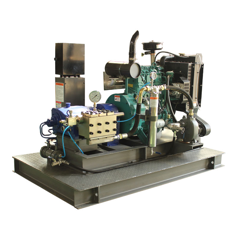
Modern plunger pumps integrate various drive mechanisms depending on application requirements. Electric motor drives dominate stationary installations, offering consistent performance with efficiencies reaching 85-92%. For mobile or remote applications, diesel engines provide autonomous operation with power outputs ranging from 15 HP to over 500 HP in industrial-grade systems.
The crankshaft mechanism converts rotational motion into reciprocating plunger movement. Crankshaft designs vary from simple single-throw configurations for single-plunger pumps to complex multi-throw arrangements accommodating 3, 5, or 7 plungers. Multi-plunger configurations deliver significantly smoother flow with reduced pulsation, often achieving flow uniformity within ±5% variation.
Performance Characteristics and Technical Specifications
Understanding the performance envelope of high pressure plunger water pumps enables proper selection for specific applications. These pumps exhibit distinctive operational characteristics that differentiate them from other pump technologies.
Pressure and Flow Relationships
Plunger pumps maintain nearly constant flow rates regardless of discharge pressure, a defining trait of positive displacement technology. Flow capacity depends primarily on plunger diameter, stroke length, and operating speed. Standard industrial units typically deliver flows between 5-200 liters per minute while generating pressures from 1,000-15,000 PSI.
The relationship between these parameters follows the fundamental displacement equation. For a single-acting single-plunger pump, theoretical flow equals the plunger cross-sectional area multiplied by stroke length and stroke frequency. However, actual delivered flow accounts for volumetric efficiency, which typically ranges from 85-95% in well-maintained pumps, accounting for valve leakage and fluid compression.
Efficiency and Energy Consumption
Overall pump efficiency comprises volumetric, mechanical, and hydraulic components. Modern high pressure plunger water pumps achieve total efficiencies between 70-85% across their operating range. This performance level significantly exceeds centrifugal alternatives when handling high-pressure applications, where centrifugal efficiency often drops below 50% at elevated pressures.
Energy consumption scales directly with pressure and flow requirements. A pump delivering 50 L/min at 1,000 bar requires approximately 85 kW of input power, assuming 80% overall efficiency. Understanding these power requirements ensures proper electrical infrastructure or engine sizing for intended applications.
| Pump Configuration | Typical Pressure Range | Flow Capacity | Efficiency |
|---|---|---|---|
| Single Plunger | 1,000-3,000 PSI | 5-30 L/min | 75-80% |
| Triple Plunger | 1,500-15,000 PSI | 20-150 L/min | 80-85% |
| Quintuple Plunger | 2,000-20,000 PSI | 50-300 L/min | 82-88% |
| Ultra-High Pressure | 20,000-40,000 PSI | 5-50 L/min | 70-78% |
Industrial Applications and Use Cases
High pressure plunger water pumps serve critical functions across diverse industrial sectors. Their ability to generate concentrated energy in water jets enables applications impossible with conventional cleaning or processing methods.
Surface Preparation and Cleaning
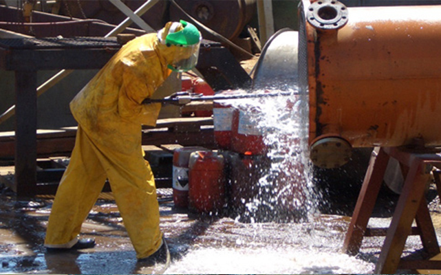
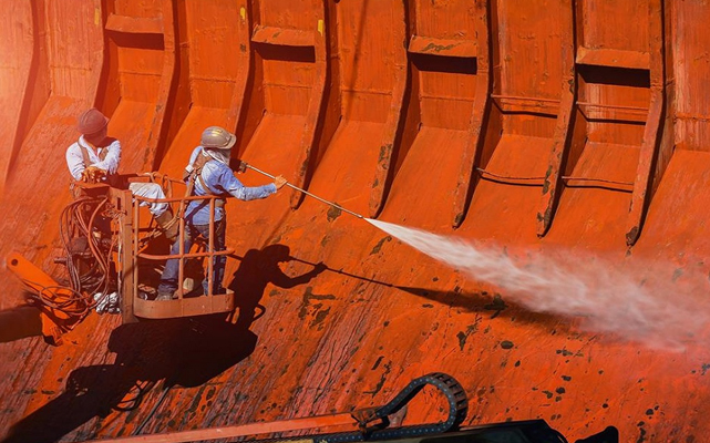
Industrial cleaning represents the largest application segment for these pumps. High-pressure water blasting removes coatings, corrosion, and contaminants from surfaces without chemical solvents. Ship hull cleaning operations utilize pumps generating 3,000-5,000 PSI to remove marine growth and prepare surfaces for recoating, completing jobs 60-70% faster than manual methods.
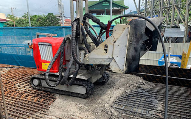
Concrete hydrodemolition employs ultra-high pressure water jets at 15,000-25,000 PSI to selectively remove deteriorated concrete while preserving sound material and reinforcing steel. This technique offers superior bond characteristics for repairs compared to mechanical removal methods, with studies showing 25-30% improved adhesion in subsequent concrete placement.
Oil and Gas Industry Applications
The petroleum sector relies extensively on high pressure plunger water pumps for multiple critical operations. Well stimulation through hydraulic fracturing requires pumps capable of delivering proppant-laden fluid at pressures exceeding 10,000 PSI into subsurface formations. Modern fracturing fleets incorporate multiple high-horsepower pumps operating in parallel to achieve flow rates surpassing 100 barrels per minute.
Pipeline cleaning and inspection preparation utilize high-pressure water jets to remove paraffin deposits, scale buildup, and internal corrosion products. This maintenance application ensures pipeline integrity and optimal flow capacity, with cleaning operations typically conducted at pressures between 5,000-12,000 PSI depending on deposit characteristics and pipe material.
Manufacturing and Processing Operations
Precision cutting and machining applications exploit the erosive power of high-velocity water jets. Waterjet cutting systems operating at 40,000-60,000 PSI can slice through metals, composites, and stone with tolerances within ±0.1 mm. These cold-cutting processes eliminate heat-affected zones and thermal distortion associated with traditional cutting methods.
Pressure testing and leak detection procedures in manufacturing quality control depend on reliable high-pressure water sources. Hydrostatic testing of pressure vessels, pipelines, and components requires controlled pressurization to 1.5 times design working pressure, with plunger pumps providing the precise pressure control necessary for accurate testing protocols.
Mining and Construction
Hard rock mining operations utilize high-pressure water jets for cutting and fragmentation. This technique, known as hydromechanical cutting, reduces dust generation by 80-90% compared to mechanical cutting while eliminating the need for explosive blasting in sensitive environments. Pumps for these applications typically operate in the 10,000-20,000 PSI range with specialized nozzle designs optimizing jet coherence.
Selection Criteria and Sizing Guidelines
Proper pump selection ensures optimal performance, reliability, and cost-effectiveness. Multiple factors influence the specification process, requiring systematic evaluation of application requirements.
Pressure Requirement Analysis
Determining required operating pressure represents the primary selection criterion. Pressure requirements derive from the specific application, material properties, and desired processing rate. Consider these typical pressure ranges:
- Light-duty cleaning and washing: 1,000-2,000 PSI
- Industrial surface preparation: 3,000-8,000 PSI
- Coating removal and concrete cleaning: 8,000-15,000 PSI
- Hydrodemolition and cutting: 15,000-25,000 PSI
- Ultra-high pressure applications: 25,000-40,000+ PSI
Flow Rate Determination
Flow capacity directly impacts processing speed and system productivity. Calculate required flow based on:
- Surface area to be processed per unit time
- Number of simultaneously operating nozzles or tools
- Required standoff distance and jet spread characteristics
- Material removal rate requirements
A common sizing guideline suggests allocating 1-2 GPM (gallons per minute) per inch of cleaning path width for surface preparation applications. For precision cutting, flow requirements depend on kerf width and cutting speed specifications.
Material Compatibility Considerations
Pump materials must withstand both the pumped fluid and environmental conditions. Standard configurations utilize:
- 316 Stainless Steel: Standard for water and mildly corrosive fluids
- Duplex/Super Duplex Stainless: Enhanced corrosion resistance for aggressive environments
- Coated Components: Ceramic or specialized coatings for abrasive media
- Specialized Alloys: For high-temperature or chemically aggressive applications
Maintenance Protocols and Troubleshooting
Proactive maintenance ensures sustained pump performance and prevents costly unplanned downtime. Implementing systematic maintenance procedures extends pump life and maintains efficiency within design specifications.
Preventive Maintenance Schedule
Establish maintenance intervals based on operating hours and application severity. Typical recommendations include:
- Daily: Inspect oil levels, check for leaks, monitor vibration and temperature
- Weekly: Verify belt tension, inspect inlet strainer, check pressure gauge calibration
- Monthly: Replace oil filter, inspect valve condition, check plunger surface
- Quarterly: Replace oil, inspect seals and packings, verify safety relief valve function
- Annually: Complete seal replacement, inspect crankshaft bearings, verify alignment
Common Operational Issues
Understanding typical failure modes enables rapid diagnosis and correction:
| Symptom | Probable Cause | Corrective Action |
|---|---|---|
| Pressure Fluctuation | Worn valves or seals | Replace valve assembly, inspect plunger condition |
| Reduced Flow Output | Inlet restriction or air leakage | Clean strainer, check inlet line connections |
| Excessive Noise/Vibration | Bearing wear or misalignment | Inspect bearings, verify coupling alignment |
| Overheating | Insufficient lubrication or overload | Check oil level/quality, verify operating parameters |
| Seal Leakage | Worn packing or scored plunger | Replace packing set, inspect plunger surface finish |
Water Quality Management
Inlet water quality significantly impacts pump longevity and maintenance frequency. Implement these water treatment practices:
- Maintain inlet filtration at 50-100 mesh minimum to prevent particulate damage
- Control water hardness below 200 ppm to prevent scale deposition
- Maintain pH between 6.5-8.5 to minimize corrosion
- Eliminate free chlorine where possible to extend seal life
- Install softening or reverse osmosis systems for challenging water sources
Safety Considerations and Operational Best Practices
High pressure water systems present significant safety hazards requiring comprehensive protective measures. Water jets at operating pressures can penetrate skin and cause severe injury, while equipment failures may result in dangerous projectile release.
Personnel Protection Requirements
Operators must utilize appropriate personal protective equipment scaled to operating pressure:
- Eye Protection: Safety goggles or face shields rated for high-pressure applications
- Body Protection: Heavy-duty protective clothing, leather or reinforced materials
- Hand Protection: Gauntlet-style gloves extending beyond wrist protection
- Foot Protection: Steel-toe boots with slip-resistant soles
- Hearing Protection: Earplugs or muffs for sustained noise exposure above 85 dB
System Safety Features
Modern pump installations incorporate multiple safety mechanisms:
- Pressure Relief Valves: Automatic overpressure protection set at 110% maximum operating pressure
- Unloader Valves: Divert flow to bypass when trigger release reduces downstream demand
- Pressure Switches: Electrical interlocks preventing operation outside safe parameters
- Guard Interlocks: Physical barriers preventing access to rotating components
- Emergency Stops: Accessible shutdown controls for immediate system deactivation
Future Trends and Technological Developments
The high pressure plunger water pump industry continues evolving with technological advancements improving efficiency, reliability, and operational intelligence.
Smart Pump Technology
Integration of IoT sensors and predictive analytics enables condition-based maintenance strategies. Real-time monitoring of vibration signatures, temperature profiles, and pressure patterns allows algorithms to predict component failures 2-4 weeks before occurrence, scheduling maintenance during planned outages rather than emergency shutdowns.
Energy Efficiency Improvements
Variable frequency drive (VFD) integration allows pump speed modulation matching output to demand. This capability reduces energy consumption by 20-40% in applications with variable load profiles compared to constant-speed operation with bypass recirculation. Advanced VFD systems also enable soft-start functionality, reducing mechanical stress during startup by 60-70%.
Advanced Materials and Coatings
Research in ceramic matrix composites and diamond-like carbon coatings promises further extension of component life. Experimental plungers utilizing silicon carbide composites demonstrate 5-10 times improved wear resistance compared to conventional ceramics, potentially extending seal change intervals beyond 10,000 operating hours in clean water applications.
Frequently Asked Questions
Q1: What is the typical lifespan of a high pressure plunger water pump?
With proper maintenance, industrial-grade plunger pumps operate reliably for 15-25 years. Major overhauls typically occur every 8,000-12,000 hours of operation, involving seal replacement, valve refurbishment, and bearing inspection. The actual lifespan depends heavily on water quality, operating pressure relative to maximum rating, and maintenance diligence.
Q2: How do I determine the right pump size for my application?
Calculate requirements by identifying your needed pressure (PSI/bar) and flow rate (GPM/L/min). Pressure depends on the cleaning or cutting task, while flow determines processing speed. Multiply pressure by flow and divide by a constant to estimate required horsepower. Consult application-specific guidelines or technical specialists to verify calculations and account for system losses.
Q3: Why does my pump lose pressure during operation?
Pressure loss typically indicates worn valves, damaged seals, or inlet restrictions. Check inlet strainer for clogging first, as this is the most common cause. If inlet is clear, inspect discharge valves for wear or debris preventing proper seating. Seal wear allows internal leakage, reducing output pressure while maintaining normal pump sound and vibration.
Q4: Can plunger pumps handle abrasive fluids?
Standard plunger pumps are designed for clean water or mildly contaminated fluids. Abrasive applications require specialized configurations with hardened plungers, tungsten carbide valves, and enhanced filtration. Some manufacturers offer specific abrasive-duty pumps with ceramic plungers and specialized seal materials. Pre-treatment filtration removing particles above 25 microns is essential for any abrasive application.