 English
 Español
 عربى
عربى


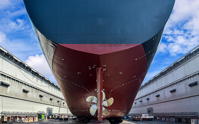

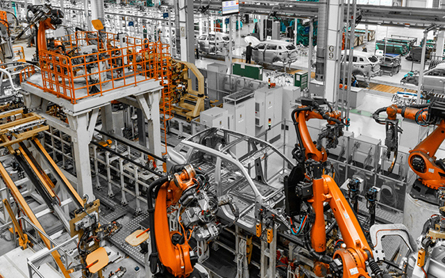
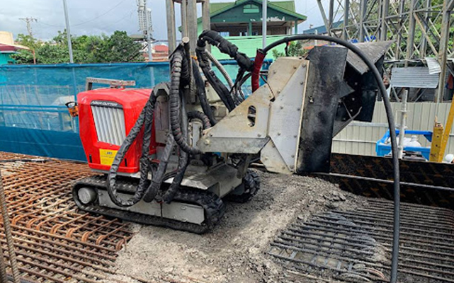
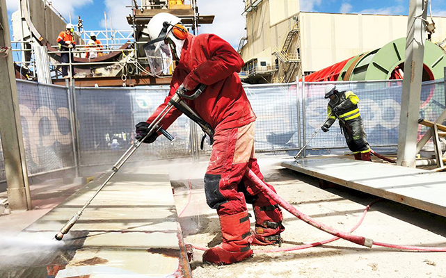
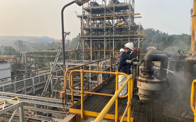
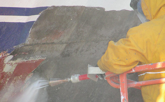
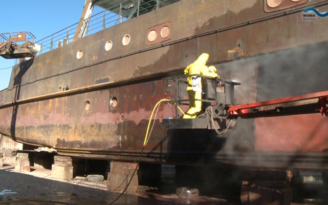
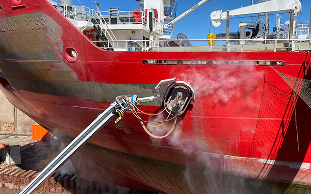
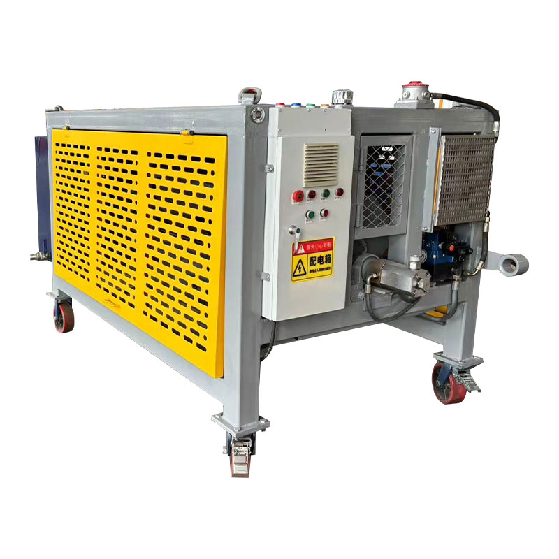
Understanding Ultra High Pressure Water Jetting Technology Ultra high pressure water jetting relies on a straightforward physical principle: water is pressurized by a triplex or intensifier pump, the...
READ MORE

Home > Catalogs > Cleaning tools > Pipe nozzles
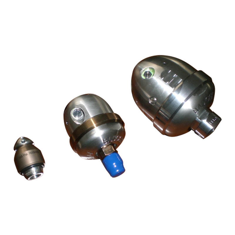
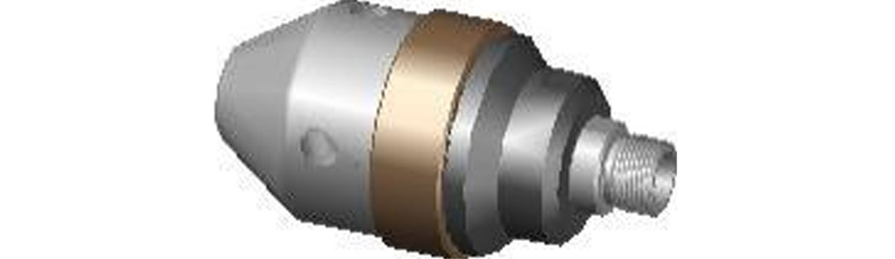
WG15 * is a series of cleaning nozzle that can clean the pipe with curvature. It adopts the patented magnetic speed limit and clearance sealing structure of fully closed type, which is used for scarring and dirt cleaning inside the pipe. The speed limit magnetic component is maintenance-free for life, and the gap
sealing makes the service life longer.
According to the inner diameter of the pipe, different types of rotating nozzle can be selected.
Technical parameter
| Model | Max working pressure | Max flow rate | Range of speed | Outer diameter | Length | Cleaning the range of the nozzle |
| WG15M | 1500bar | 80L/min | 200~1500rpm | 62mm | 136mm | ¢80~120mm pipe |
| WG15L | 1500bar | 100L/min | 200~1500rpm | 75mm | 146mm | ¢85~130mm pipe |
| WG15XL | 1500bar | 120L/min | 200~1500rpm | 98mm | 156mm | ¢120~160mm pipe |
Water quality requirements
Inlet temperature: ≤40℃; PH value: 6.5 ~ 8.5
Water filtration accuracy: ≤10 μm
WG15 * Rotating seal assembly schematic diagram and sectional view
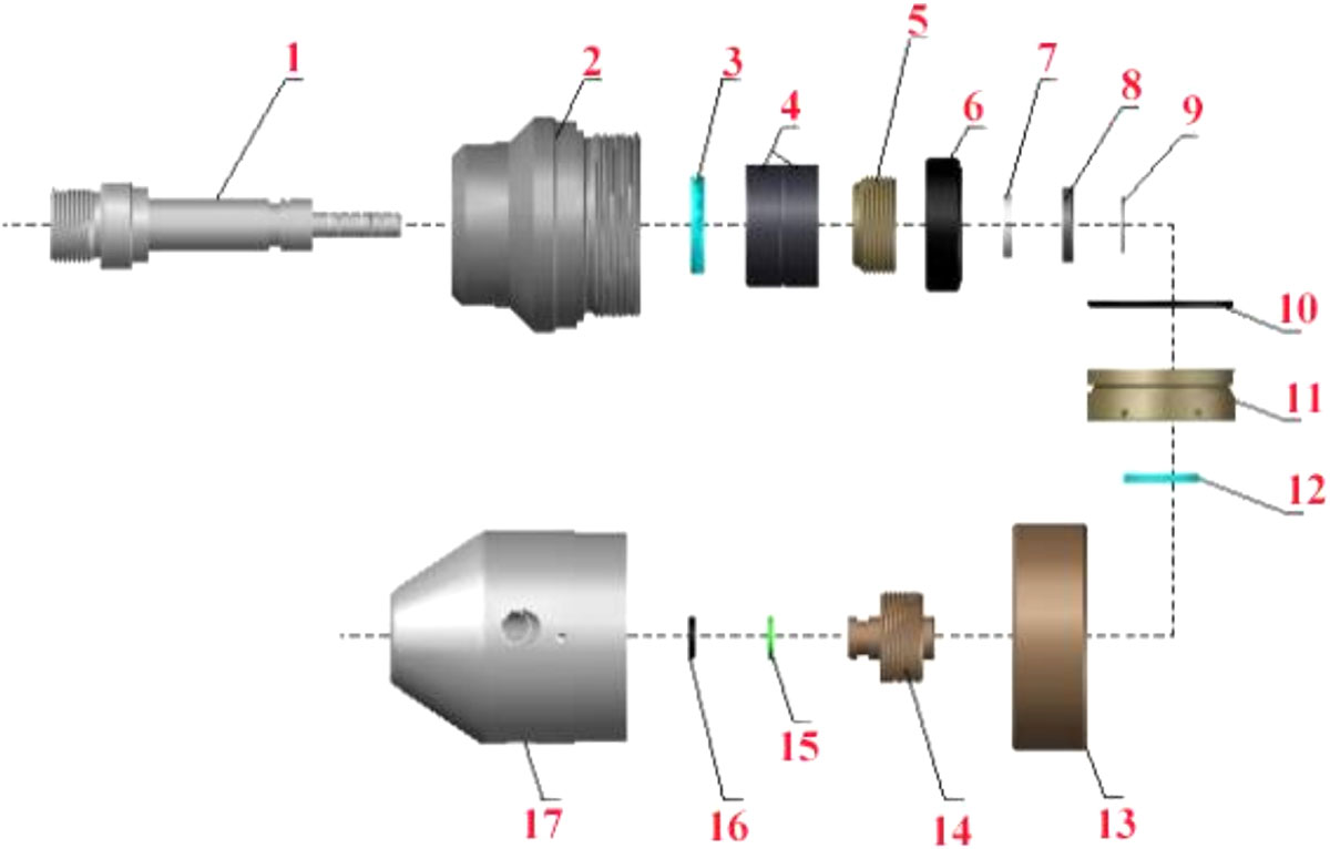
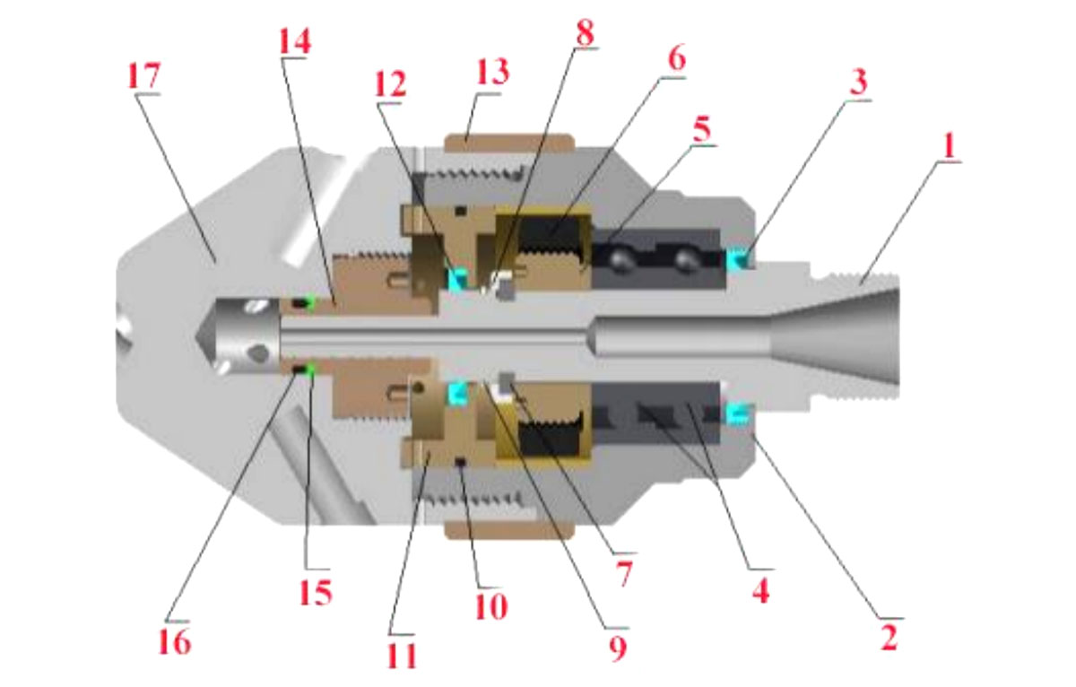
The spare parts subsidiary
| NO. | Description | Qty |
| 1 | Shaft | 1 PCS |
| 2 | Rotating housing | 1 PCS |
| 3 | Oil seal | 1 PCS |
| 4 | Bearing | 2 PCS |
| 5 | Magnet transition connection | 1 PCS |
| 6 | Magnet | 1 PCS |
| 7 | Snap ring | 1 PCS |
| 8 | Snap ring sleeve | 1 PCS |
| 9 | Circlip | 1 PCS |
| 10 | O ring | 1 PCS |
| 11 | Oil seal Skeleton | 1 PCS |
| 12 | Oil seal | 2 PCS |
| 13 | Supporting ring | 1 PCS |
| 14 | Copper seal sleeve | 1 PCS |
| 15 | Plastic seal ring | 1 PCS |
| 16 | O ring | 1 PCS |
| 17 | Rotating head | 1 PCS |
Installation process and matters needing attention
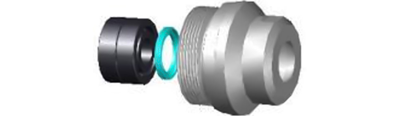
(1) Install oil seal 3 in the inner hole at the back end of the rotating housing 2, and a pair of angular contact shaft 4 (note: the installation direction of oil seal 3 is groove faces inward, otherwise the rotating housing 2 will be filled with water and damage the bearing; Note that angular contact bearing 4 is mounted in the same direction as the two bearings, with one side of the outer ring wide facing the back end of the rotating housing 2).
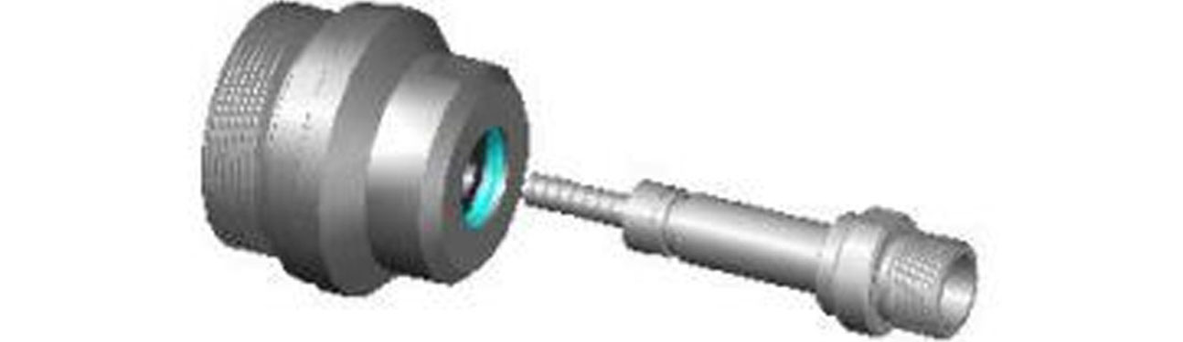
(2) Insert shaft 1 from the rear end of the rotating housing 2 into the rotating housing 2.
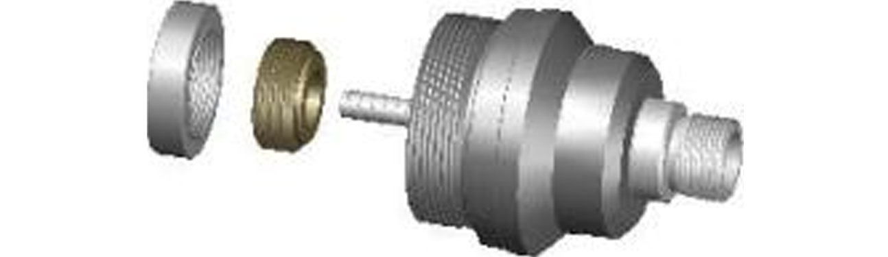
(3) Apply anti-bite agent to the screw grain of shaft 1 and magnetic iron component (including: magnet transition connection 5 and magnet 6), tighten the thread of magnet 6 and magnet transition connection 5 (note: positive rotation of thread), then thread the magnet 6 component through the front of shaft 2 and tighten the thread of shaft 2 (note: positive rotation of thread).
(4) Install snap ring 7 and snap ring sleeve 8 in the ring groove of shaft 1, and then fix them with circlip 9.
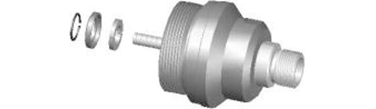
(5) Insert the oil seal skeleton assembly (including: O ring 10, oil seal skeleton 11, and oil seal 12) from the front end of shaft 2 and install it in the rotating housing 2.
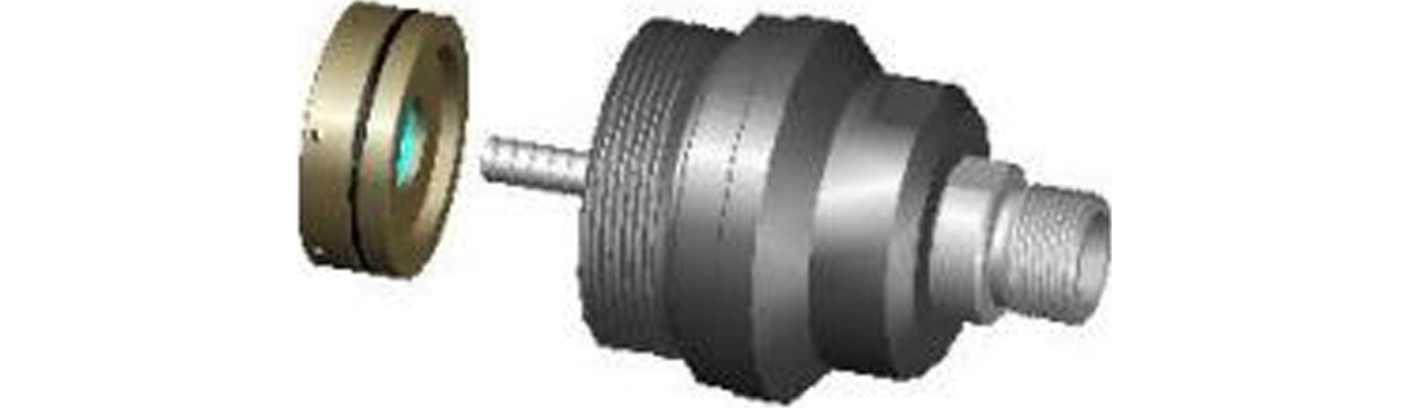
Remarks: installation instructions of oil seal skeleton assembly.
The O sealing ring 10 was installed in the annular groove on the outer side of the oil seal skeleton 11.
Install the oil seal 12 in the inner hole groove of the oil seal skeleton 11 (note the installation direction of the oil seal 12, groove faces inward).

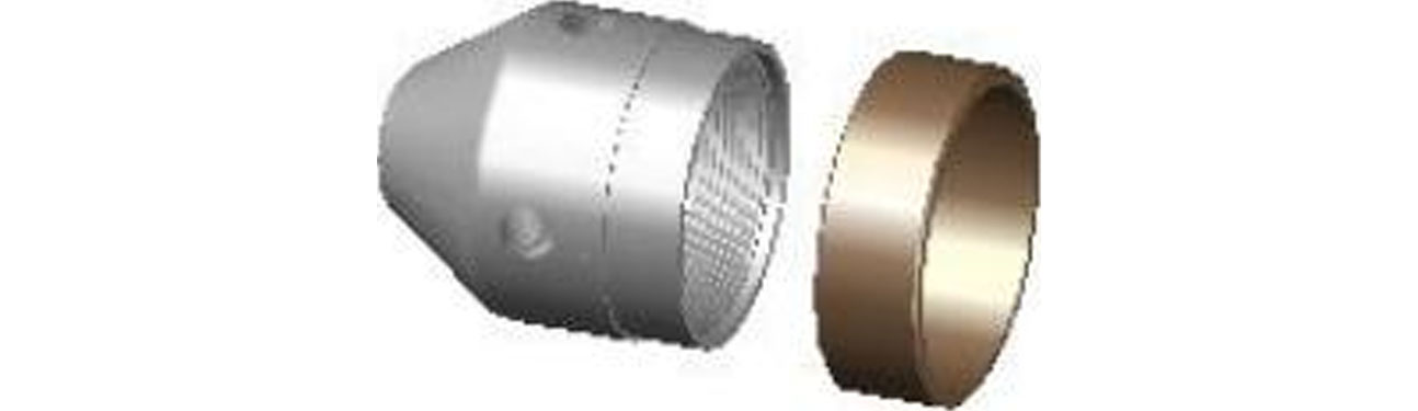
(6) Install the O ring 16 and the plastic seal ring 15 successively in the ring groove at the front of the copper seal sleeve 14.(note the installation sequence of O ring 16 and plastic seal ring 15. O ring 16 is installed on the outside of the ring groove of copper seal sleeve 14.Pay attention to the installation direction of plastic seal ring 15, with groove side towards the O ring 16).

(7) Apply anti-bite agent to the thread of the copper seal sleeve 14 and the inner hole thread of the rotating head 17, then screw the copper seal sleeve 14 into the inner hole thread of the rotating head 17 and tighten it (note: positive screw thread).

(8) Insert support ring 13 from the back end of rotating head 17 and install it outside of rotating head 17.
(9) Finally, anti-bite agent is applied to the front end of the outer thread of the rotating housing 2 and the back end of the inner thread of the rotating head 17. The front end of the sub-assembly shaft 1 completed in step (5) is inserted into the inner hole of the copper seal sleeve 14 of the rotating head 17, and then the threads of the rotating housing 2 and the rotating head 17 are tightened (note: the thread is positive rotation).
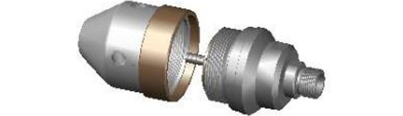
(10) The above steps completed the assembly process of WG15*nozzle.
6. Disassembly process and matters needing attention
(1) Use an open-end wrench to clamp the rotating head 17 and the rotating housing 2 to the milling side, and then screw the rotating head 17 out of the spiral pattern of the rotating housing 2 (note: the thread is positive rotation), and remove the support ring 13.
(2) Insert the circlip pliers into the back end hole of the copper seal sleeve 14 in the rotating head 17, loosen the thread (note: the thread is positive rotation), screw out the copper seal sleeve 14, check whether there is any wear in the copper seal inner hole, if there is any wear, replace it if there is serious wear; At the same time, check whether the O ring 16 and plastic seal ring 15 on the copper seal sleeve are damaged, if there is damage, please replace them, otherwise the seal will not work.
(3) Remove the oil seal skeleton 11 components from the inner hole of the front end of the rotating housing 2. Remove the oil seal 12 and O ring 10 from the inner hole and outer ring groove of the oil seal skeleton respectively, and check whether there is any damage to the oil seal 12 and O ring 10. If there is any damage, please change it, otherwise water will enter the housing 2 and damage the bearing.
(4) Use the external pliers disassemble the circlip 9 from shaft 1 and disassemble the snap ring sleeve 8 and snap ring 7 from the ring groove of shaft 1 .
(5) Remove the connected magnetic assembly from shaft 1 and check whether there is any dirt attached to the magnet. If there is, please clean it.
(6) Pull shaft 1 out from the rear end of the housing horizontally, check whether there is any wear on the outer surface of shaft 1. If there is any wear and tear, please change it.
(7) Carefully remove the angular contact bearing 4 from the inner hole of the rotating housing 2 and check whether the shaft bearing is damaged. If damaged, please replace it.
- 7 -
(8) Remove the oil seal 3 from the inner hole back end of the rotating housing 2. Check whether the oil seal 3 is damaged. If it is damaged, please replace it.
The above steps have completed the whole disassembly process of WG15* nozzle.
Notes:
•Pay attention to the installation direction of the angular contact bearing during the assembly process, if installed in reverse, the nozzle will not be used;
•During assembly, pay attention to the installation direction of the oil seal. If installed in reverse, the water entering the nozzle cannot be sealed, the bearing will be damaged and the nozzle head will not rotate.
•During the assembly process, pay attention to the installation position of O ring and plastic seal ring. If the O ring and plastic seal ring are inverted, it will not be able to play a sealing role. Meanwhile, pay attention to the installation direction of the plastic seal ring.
•All seals inside the rotating nozzle are easy to wear and tear. During the use of the rotating nozzle, it is necessary to pay attention to the leakage of the nozzle at any time. If any abnormality is found, it is necessary to check whether the seal is damaged in time.
7.Common problems with rotating nozzle
(1) rotating nozzle cannot rotate;
The reason:
A) Internal bearing damage (normal damage or early damage caused by water inflow due to oil seal failure);
B) The nozzle used to generate eccentric torque is blocked or the installed nozzle aperture is too small to achieve the starting torque;
(2) Work pressure drops rapidly;
The reason:
A) Nozzle damage;
B) The nozzle is loose, resulting in loose sealing;
C) Cracks appear in shaft or copper seal sleeve.
(3) work pressure decreases slowly;
The reason:
A)The nozzle is worn normally;
B)Shaft or copper seal sleeve is worn.
8. Center cage
The central retainer protects the rotating nozzle working in the pipe and balances the spray distance of the nozzle. Adjustable range is 150~300mm.



Understanding Ultra High Pressure Water Jetting Technology Ultra high pressure water jetting relies on a straightforward physical principle: water is pressurized by a triplex or intensifier pump, the...
READ MOREWhy Hose Size Is the Hidden Variable in Pressure Washer Output Most buyers focus on pump horsepower, PSI ratings, or nozzle style when they shop for cleaning equipment, yet the hose connecting the pu...
READ MOREIndustrial pipe maintenance, structural lining preparation, and municipal mainline clearance operations rely heavily on hydro-mechanical force. While the high-pressure displacement pump serves as the...
READ MOREWhen a main sewer line backs up, most homeowners face a choice between two methods: snaking or hydro jetting. While snaking has been the default for decades, main sewer line hydro jetting has grown i...
READ MOREUnderstanding high-pressure water jetting for professional drain cleaning and infrastructure maintenance. 1. Defining the Core: What Is a Sewer Jetter in Plumbing? A sewer jetter refers to a sp...
READ MORE
